UE4 Application HMI#
The UE4 applications offer several features to control the visualization of both the scene and the simulated drone.
Once the parrot-ue4-xxxx window appeared, you can select
Edit > Keyboard Shortcuts (or pess F1) to display a list of
available keyboard commands.
Cameras#
There are two types of cameras:
Unreal cameras: used to visualize the scene, can be manipulated
Embedded drone cameras: are embedded in the drone, can only be visualized
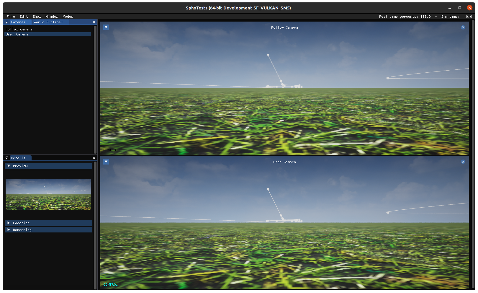
Cameras can be displayed by dragging and dropping them from the Cameras
window onto either the main window or one of the three subwindows located at the
bottom of the main window.
Example: Drag and drop camera
Each view can be maximized to take out the whole window by clicking on the arrow
inside the view. You can also quickly hide the rest of the UI by selecting
Show > Hide Panels or by pressing F10.
Unreal cameras#
Unreal cameras let you navigate throughout the scene. You can move the camera
using the keyboard (check the list of keyboard shortcuts by pressing F1 to
get the list of keys to move the camera).
Two kinds of Unreal cameras are available:
Follow Camera - the camera is locked on its current target location. If the target moves, the camera moves the same way. The control over the camera location using the keyboard changes the offset in between the target and the camera. By switching to
Velocity-basedmode, available in theTransformsection, the follow camera is placed along the velocity vector of a selected target, regardless of the body orientation.User Camera - the camera has no constraint in translation. The user can move it to any place in the scene. The traveling speed is much higher than for the follow camera. By switching to
Ground Observermode, available in theTransformsection, the user camera orientation gets locked to the direction of a selected target. While in this mode, the camera can still be translated in all directions.
Note
A target can be either the simulated drone or one of the AMS actors present in the scene.
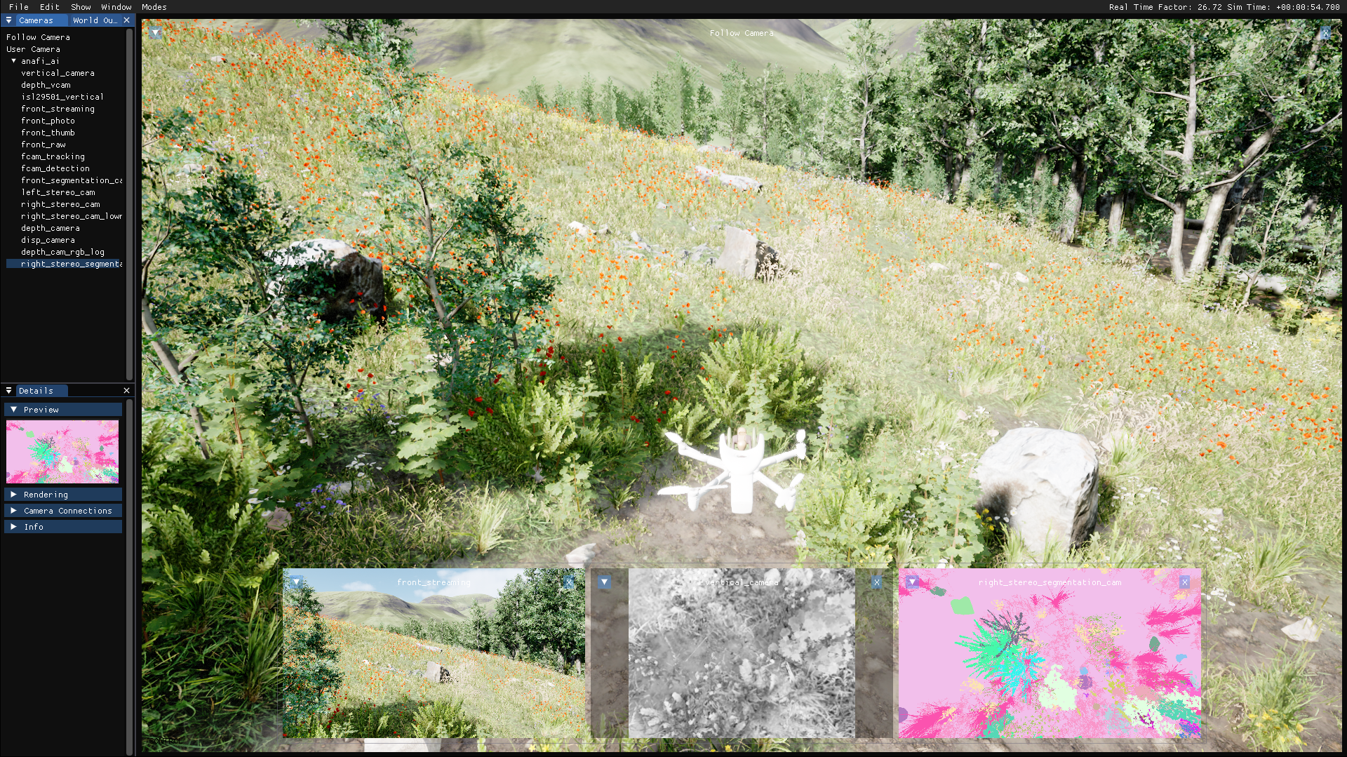
Embedded drone cameras#
Parrot Sphinx is able to display at run-time any camera included in the drone. It can also display renderings from “virtual” cameras that come in addition to the real ones.
Warning
Bear in mind that displaying one or more embedded cameras may have in some cases a severe impact on the simulation speed.
By default, drone cameras fit to the window they are in. To use the native
resolution of the camera, click on the arrow and uncheck the Fit to Window
item.
The field of view of the camera can be visualized in Unreal cameras by
selecting Visualize in the Rendering section in the Details panel of
the camera you are interested in.
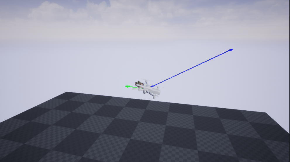
Drone behavior#
To cover some specific needs, it is possible to toggle the display of
linear acceleration and velocity of the drone. These are represented by colored
arrows. You can do this by choosing Velocity and Acceleration from the
Show menu on the menu bar. By default, the Trajectory is always
displayed when obstacle avoidance is activated.
Spline Editor#
This mode gives the ability to to interactively create custom paths that actors
can follow.
You can toggle this mode by choosing Spline Editing from the Modes menu
on the menu bar. You can also press the F2 key.
When you toggle the spline editor mode, the user camera will switch to the
User Camera automatically and you will not be able to use other camera modes
until you quit the editor.
The spline editor is designed to show the user what his path will look like in the simulation.
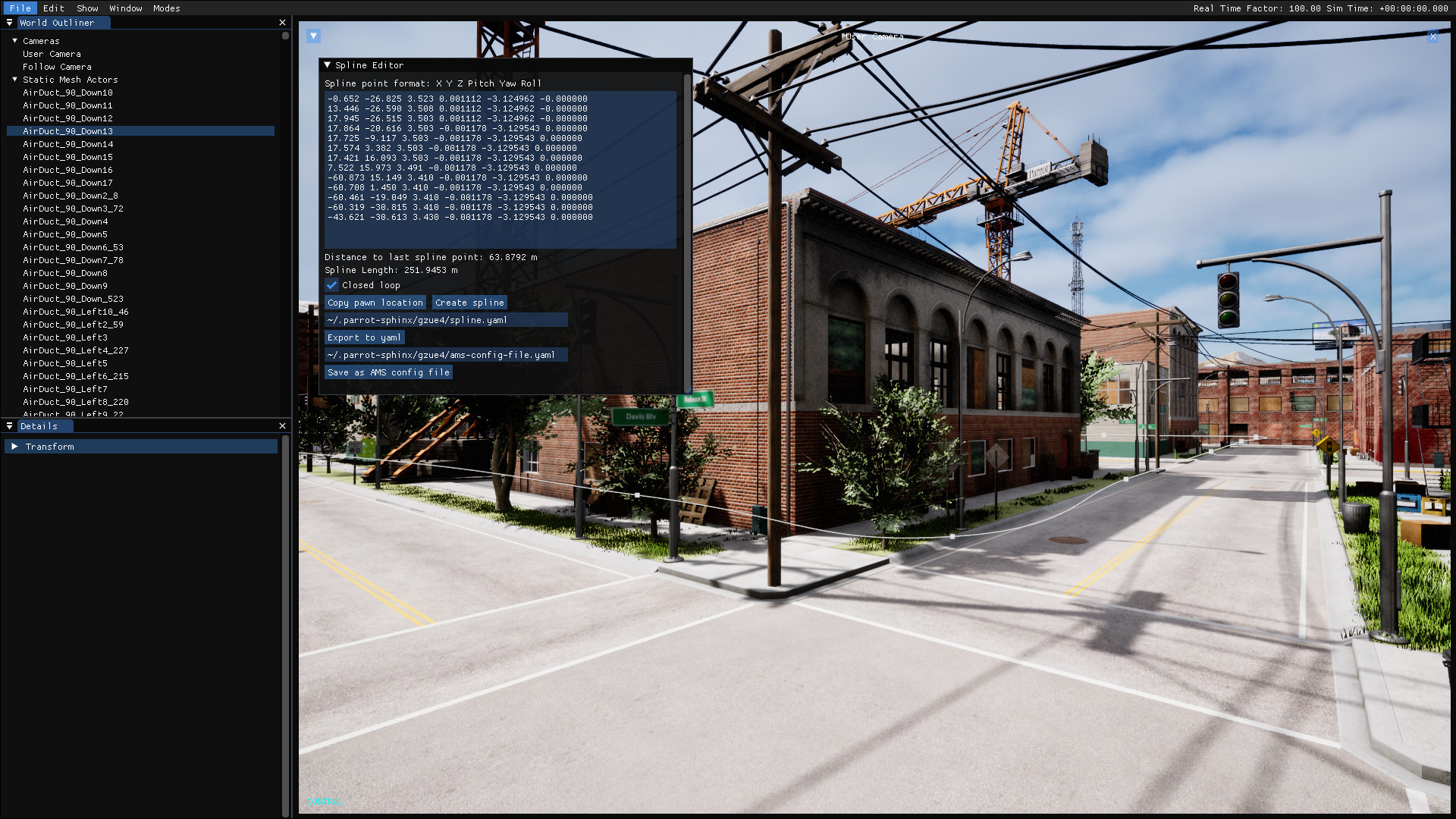
The spline editor is composed by:
Spline points text box - An editable text box where the selected spline point coordinates appear. Within this box, every existing point can be manually adjusted or removed, some others can also be manually added. Each line represents a spline point. The spline point format is
X Y Z Pitch Yaw Rolland those values are expressed in Gazebo frame.Closed loop - A check box to set whether the created path is a closed loop or not.
Copy pawn location - Copy the location and the orientation of the user camera to the spline points text box.
Create spline - Create or update the path using the list of spline points from the spline points text box.
Exported file path - A text box where you write the path of the file you want to export into. Relative paths are allowed and they are relative to from where you launched the app.
Export to yaml - Export the created spline to a
.yamlfile under the path from the text just above.AMS config file path - A text box where you write the path of the AMS config config file you want to export into. Relative paths are allowed and they are relative to from where you launched the app.
Save as AMS config file - Export the created spline to a
.yamlfile under the path from the text just above.
Example of exported file:
# Splinepoint format : X Y Z Pitch Yaw Roll
SplinePoints:
  - 178.363 -516.087 1.140 -0.020975 3.081684 -0.001515
  - 172.473 -515.734 1.016 -0.020975 3.081684 -0.001515
  - 166.793 -515.864 1.028 0.001929 3.077103 -0.001515
  - 160.206 -515.119 1.040 0.001929 3.077103 -0.001515
  - 155.106 -517.661 1.054 0.001929 3.077103 -0.001515
  - 158.600 -520.390 1.051 0.001929 3.077103 -0.001515
  - 164.825 -520.041 1.038 0.001929 3.077103 -0.001515
  - 171.881 -520.197 1.024 0.001929 3.077103 -0.001515
  - 177.731 -519.836 1.011 0.001929 3.077103 -0.001515
To cover several usages, the exported YAML file is formatted in the most generic
way.
Therefore, if you want to use the generated spline as a path to be followed by
an actor, you need to choose Save as AMS config file to match the
AMS configuration format.
Note
Because the text box is editable, you can add more information for each spline point at the end of their corresponding line like the attitude of the pedestrian or the speed of the vehicle. They will be contained in the exported YAML file to help you create the path.
Getting details from any 3D object#
You can find the list of all objects in the scene in the World Outliner
panel.
When you select an object from that list, it will be outlined in yellow color
and the following information will be shown in the Details panel:
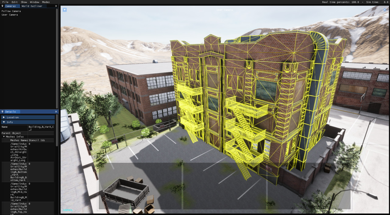
Name - The name of the object in the scene.
Parent Object - The name of the parent object if this object is attached to another object, otherwise it is empty.
Meshes Names - The name(s) of the mesh(es) of the object.
Stencil Ids - For each mesh, the corresponding stencil ID.
If the selected object is a Parent object, all its attached children are outlined along with it, providing a view over the whole combined object.
Besides, from the User Camera window, You can also select any object by pressing on the mouse left button, which - among other things - can be convenient to create a stencil file (see segmentation camera for more details).
Setting the user camera location and orientation#
It is possible to set the location and the orientation of the user camera
without moving it manually. To do so, select the User Camera in the
Cameras window and open the Transform section in the Details panel.
You can now edit its location and rotation. The coordinates are expressed in
Gazebo frame.
You can also open the console using the ; key (semicolon) and write one of
these commands:
AbsoluteTranslate <X Y Z>
AbsoluteRotate <Roll Pitch Yaw>
RelativeTranslate <X Y Z>
RelativeRotate <Roll Pitch Yaw>
These are the descriptions of each command:
AbsoluteTranslate <X Y Z> - This command places the user camera at the location with coordinates X Y Z according the world coordinate system.
AbsoluteRotate <Roll Pitch Yaw> - This command sets the orientation of the user camera to Roll Pitch Yaw according to the world coordinate system.
RelativeTranslate <X Y Z> - This command translates the user camera by the given offset. The offset <X Y Z> is expressed in the horizontal local frame, which can be defined as the world coordinate frame being rotated by the current yaw of the camera.
RelativeRotate <Roll Pitch Yaw> - This command adds an offset to the camera’a actual orientation according to the world coordinate system.
Note
All commands input values are expressed in Gazebo frame.
Any missing input will take 0 as default value.
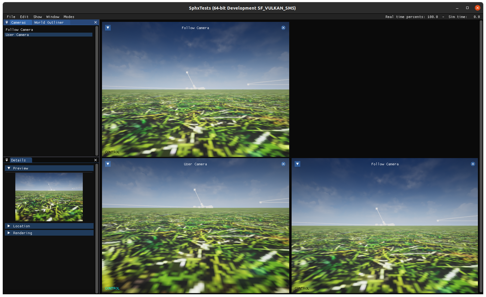
Layouts#
You can select the amount of visible cameras by changing the layout in the
Modes menu. Currently each mode gives you between 1 and 4 panels.
It defaults to 1 panel.
Each layout is fixed, but you can rearrange cameras as you want, and their last position will be kept between relaunches of the application.
The floating panel is automatically removed when multiple cameras are shown. You can remove it in the single panel mode, by maximizing the camera.
Examples#